**** Just moved this site from a now defunct server - some links are broken - mending... and updating a little, after over a decade..., images are rubbish aren't they?
**** OK, updated a few of the images - better detail - also showing revised side cheeks in sheet Aluminium, more in keeping with the rest, and Al strip speaker leads (ex beer can )
finally, a BIG nod to Nelson's parting comment at the very bottom of the original article: "Running greater current and parallel channels improves the damping factor in the same kind of proportion. In the test case, the damping factor went from about 8 to about 30."
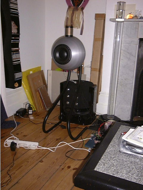
This amp is built around a fabricated heatsink, and runs two Zen Revisited stages per channel (just strapped together at i/p and o/p)
to cope with my 4ohm speaker balls - double current demands over
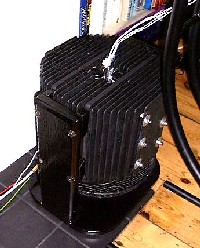
an 8 ohm rig. The heatsink is the amp, so to speak, in that it is also the complete chassis and 'substrate' on which all the electronics sit (all point to point, spaghetti-like, as it's so simple). The pic here shows a complete mono-block, comprising two ZR amps, each on a semi-circular heatsink, placed back-to-back (electronics in the centre - i/p below, o/p at the top, clean DC power via umbilical from remote PSU) to form the big cylindrical heatsink seen here. Each mono block is dumping 400W - 2 Zen stages each
running at 4amp bias, 50v rail. This combo can manage 50W RMS
into 4ohm before clipping. With thanks to Nelson for the tips
along the way and making this information available to us who
love to mess with this stuff. Oh, and it sounds superb too - enjoying it now as I tinker with the website. Really surprising just how good a 128kbps Internet radio station - http://www.acousticfm.com/ - sounds over nice gear.
I'm
happy to be emailed with any queries or comments not answered
here - a lot of time and head scratching has gone into this - it
would be a shame not to share it....
Bi-amp/wire update: So I tried bi-wiring from each of my
'strapped' gain stages to the speaker instead of strapping at the
amp and single wiring. Wow - even over appx 2ft it sounds better
- seemingly more in control than before - cleaner highs.
Zen Revisited is mated with a Bride of Zen
pre-amp. Pass Bride of Zen - original article Both share a single remote PSU box, and have their own umbilicals, from independent power supplies, see more below.
This
is a wonderful little pre-amp!! Note the low load impedance seen
by the Bride (500 ohm appox) due to the 2 strapped Zen Revisited
stages doesn't appear to hurt the Bride, although it does clobber
the max gain a bit - see Nelson's bit re the gain being also
dependant on the load resistance. When the volume isn't at max,
the Bride's gain comes up as the attenuator buffers it from the
Zen's 500ohm. I calculated resistor values for a stepped
attenuator taking into account the Zen's i/p impedance - but
forgot to factor in the Bride's gain drop at max volume. I don't
find the 3dB steps I implemented for my 11 way unit too course.
It's an ex WW2 rotary switch (just HAD to use it), it has superb
big silver (?) plated contacts, from some radio gear I think.
It's clunkyness complements the Zen philosophy brilliantly!
Feel free to mail me, and don't forget to enjoy the music
along the way...
(Click on the pics for more detail)
Introduction.
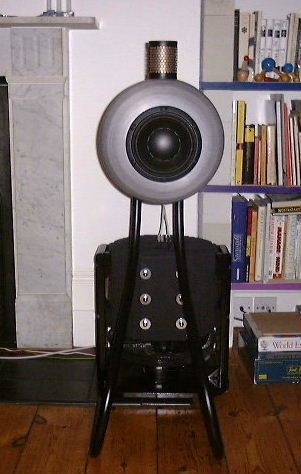
The black thing behind the speaker (Gallo
Nucleus Solos) is a mono block. The PSU and preamp are
remote. Each mono block is two Zen stages in parallel - strapped
at i/p and o/p - literally, but o/p strapped at the speaker
terminals to benefit from bi-wiring - see below. Note that the act of strapping the two stages together also improves the gain and lowers the distortion. As regards setting these up, I used a software scope/spectrum analyser (Visual Analyser 8), via the line input of my laptop, first setting each stage independently for minimum harmonics (on a 1000Hz test sine wave), then again with them strapped together (when I noticed the gain improvement). The test load was the actual speaker to be used (ear plugs recommended!).
Make sure the amp is allowed to warm up properly before final setting up.
Using the (Windows 7) laptop to set the amp up:
= I had to disable all 'enhancements' on the generic 'microphone' input before getting a clean feed - it was trying to be clever but failing massively!
= Watch you don't overload the line-in - I was using only about half max volume (or use a resitor attenuator) in the feed to line-in. It's obvious when clipping occurs if you are using a software scope.
= The gain of the line-in is adjustable too - see the input device's properties page. I also have 'microphone boost' on mine - set it to minimum.
= On my laptop, plugging a jack into the line-in disables the internal mic. Do make sure the mic is disabled - it'll make for some v.weird effects!
= I used the laptop on battery to avoid any issues with earth loops (or worse!), mains hum etc.
= Connect the ground on the amp (speaker '+' output in this amp) to the ground of the laptop line-in, although it may not matter if the laptop is on battery.
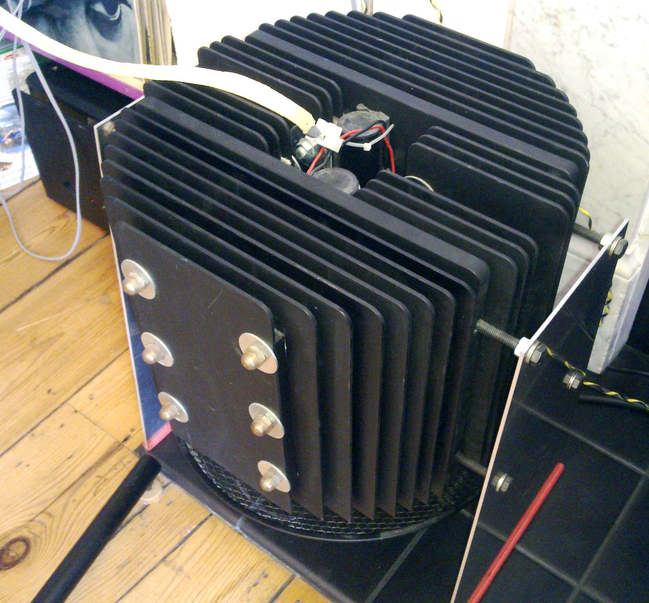
Top
view - shows the two adjacent semi-circular heatsinks -
one per Zen stage. (Back of a speaker ball at bottom of pic).
They are two completely separate constructions. The inner 3 fins
of each are split, forming a vertical channel down the middle in
which the electronics sits - see other pics. The MOSFETs are
positioned centrally in these channels on the outboard side of
the 12.5mm plate (I used TO3). Speaker wires come straight out of
the top (not bi-wired in this pic - see comments above). Input
comes in from underneath (not visible here) - strapped together
on the way. Fan (not visible here) is below, blowing upwards, see
pic below. The two silver vertical bars visible are the unpainted
tops of the two rows of Al spacer bars which form the thermal
pipe between all the sink fins. Each row of spacer/fins is
clamped together by 3 long M8 studs. The dome nuts are visible in
this pic at the 6:30 & 5:30 positions. The ends of the big
o/p caps are visible in the middle - I used a single (bypassed)
10,000uF from a previous project. The wooden cradle supporting
the sinks via M8 bolts can be seen at either side. It's something
to grab hold of when moving this animal too - each mono block
weighs about 25Kg!
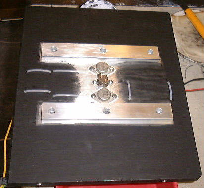
Top
view closer. The thick plates (12.5mm Al) carry the
MOSFETs and get over the problem of all that heat in a
concentrated area. This works brilliantly. Suppose these plates
only need to extend as far as the 'thermal pipe' spacers to the
rest of the sink - their thickness is wasted after that. The
speaker outputs are strapped at the 'chocolate block' connector
in this pic - now bi-wired and strapped at the speaker terminals.
MOSFETs: I used EC-20P16
and EC-20N16 devices (250W 160V) by Exicon, (Update May 2013: Hmm, looks like these are not around now, but see this link for a good starting point. Mine were still from Profusion) from Profusion
in the UK. The are lateral devices that claim to have thermal
characteristics that discourage run-away. I believe these 250W
devices have two paralleled devices inside, so effectively twin
versions of the 125W devices in one case. They certainly seem to
work in this design, and seem pretty rugged too (Update May 2013: Absolutely cast iron no problems, but suspect massive heat sinking helps here). Availalable in
TO3 or a flat plastic format (like the IRF devices, but I think
it's a little larger).
Thermal protection: I mounted 50C N/C thermal
switches adjacent to the MOSFETS on the same Al Plate. This gives
a reasonable margin for those hot days (yes, even in the UK) but
will cause complete system shutdown if a fan fails or someone
drops a sweater on top of an amp. CAUTION: Remember those
school physics lessons and how well matt black surfaces radiate
heat so well? The good old principal of duality says it works in
reverse too - an amp whose heatsinks are sitting in strong
sunlight will seriously compromise (even
reverse) the 'sink performance. I was reminded of this when fin
painting and putting them under a roof window to dry - they got a
LOT hotter than they do working as sinks with the amp.
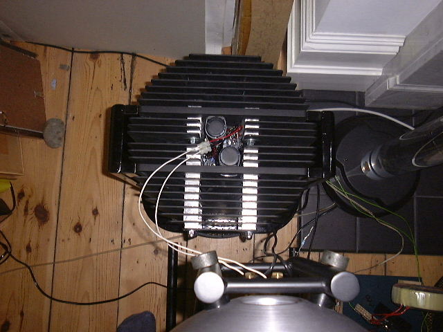
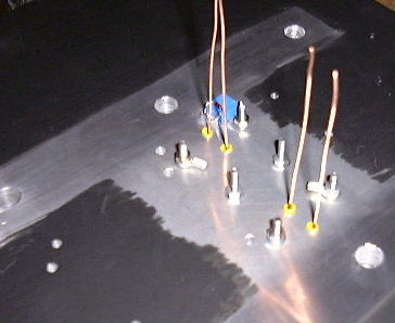
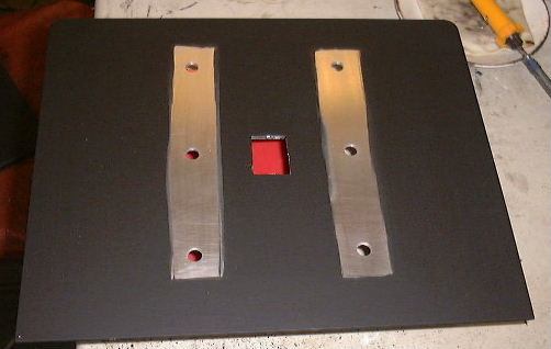
MOSFET
leads coming through from back. The two bolts in centre are for
the thermal switch. Have to be careful with insulating the bolts
when going through this thickness of plate. Also pre-solder
extensions to the MOSFET leads and sleeve insulate them. Note
cleaned unpainted surfaces left for thermal joints. Simply put a
spacer down & paint around it.
MOSFETs and thermal switch between them. Cable ties holding big
caps.
A word on testing - DOUBLE CHECK the MOSFETs are properly
mounted and tightened down - they get extremely hot
extremely fast otherwise!
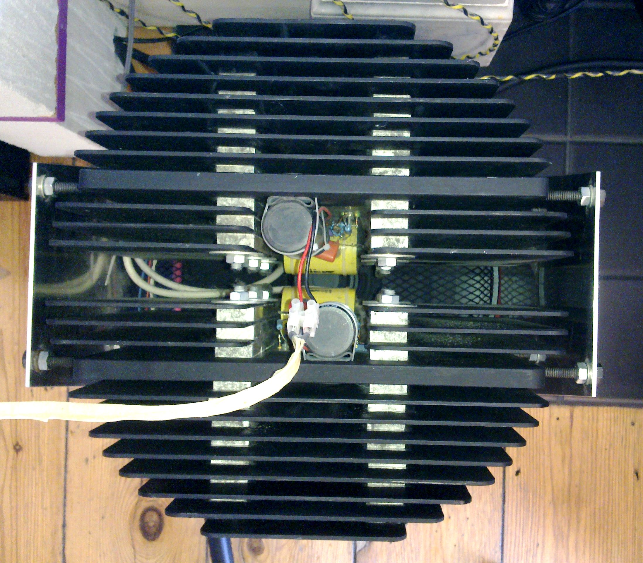
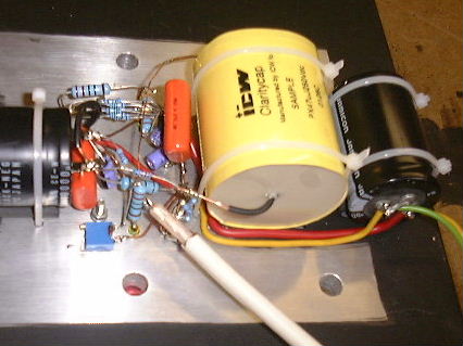
Detail of point to point wiring and humungous yellow ICW i/p cap.
The left hand black cap is the o/p, the right hand black cap the PSU smoothing (the
others are in the remote PSU). Final decoupling is (rh) orange
2.2uF polystyrene and 47uF elec below - nice and local to where
it matters. The whole lot is star (more or less) earthed,
including the plate, adjacent to the end of the wt coax i/p lead.
(+) Speaker cable comes in here too, and (-) direct to o/p cap
terminal and f/b point. The big caps are sitting on bits of
bicycle inner tube to insulate them (thermal) from the plate and
hold them off a little too.
Instability problem:
I previously had the sinks grounded via rather a long wire,
instead of right at the star earth point as above. This was
actually OK when I had a little electrolytic 47uF as i/p cap.
Changing this to the big ICW film cap immediately resulted in
some nasty HF instability on the top portion only of the (+Ve)
output peaks, under heavyish load (but well before clipping). I
suspect this has to do with the extra lead lengths to wire this
physically big cap in. Also as per original design there was no
gate resister in the gain MOSFET. Instability also changed on
touching the heatsink. Yuk.
Instability solution: (thanks to those who
helped me out on the forum on this)
1) Add 220ohm gate resistor to gain MOSFET (just like for the
current source). Site this as near the gate lead as possible.
2) Ground sink directly at the star earth point and dispense
with previous ground scheme.
3) Pay proper attention to PSU decoupling, particularly HF and
make sure it is very local to the rest of the electronics. See
note above re 2.2uF and 47uF caps.
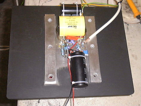
General view of completed stage before fin assembly. Speaker
wires (blk/red) go out of what will be top of assembly - straight
up to ball terminal nearby - no long speaker cables here! See pic
below.
A
fin awaiting assembly - this one's adjacent to the main plate -
centre hole for thermal switch - it's thicker than the spacer
bars.
The above pics show one Zen stage and the general layout - one
of the PSU electrolytics at the bottom, MOSFETs and other bits in
middle, o/p cap at top. All strapped (cable ties) to the heatsink
main plate. Rest of PSU stuff including another pi filter output
electrolytic is in remote PSU box.
One channel - minimal speaker cables bi-wired from the 2
paralleled stages.
Shows the fan below - a stripped down 30cm room fan unit running
ever so slowly (two in series does the trick) so it's virtually
silent. This uses original motor - at a tiny fraction of it's
capacity - could drop the whole thing 10cm with a smaller motor -
would it still be so quiet I wonder?
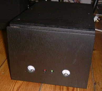
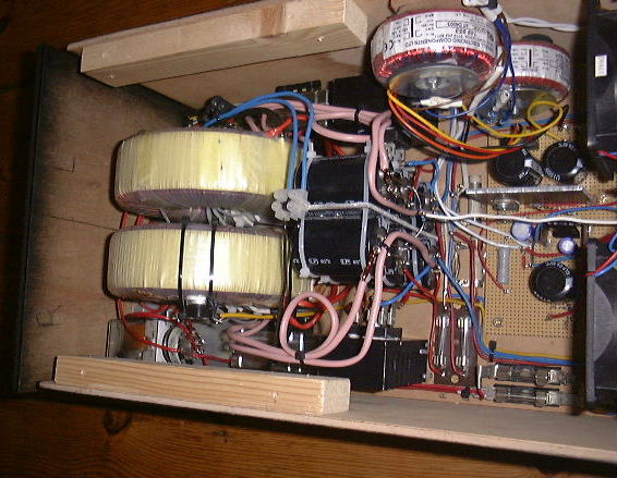
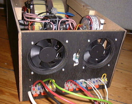
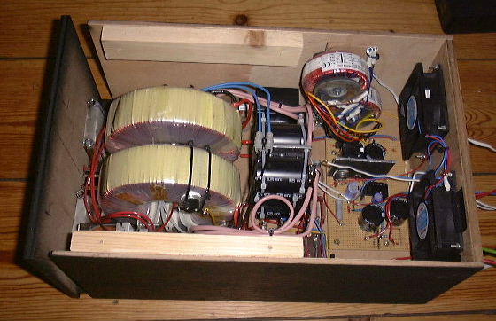
The PSU
The PSU is built into a separate box (fan cooled - I messed up
on specifying the transformers. The air comes out of that slot
formed by the top/sides not quite meeting the front panel) - also
houses the PSU for the Bride and an aux 12V PSU for fans, relays,
meter back lighting etc. (thanks to Nelson for the inspiration on
back lighting - pity they came out wt in the pics - they're a
nice cool red!).
Each pair of (paralleled) stages is run off it's own PSU
delivering 50V DC at 8amps. Each PSU has the original 2mH choke,
but I beefed up the caps a little - 2*10,000uF on the Pi filter
i/p, then 1*10,000uF in the PSU box on the PI filter o/p, and
then a further 10,000uF local to each Zen strapped to the
heatsink - see the pics. I cannot hear or scope (may be beneath
noise of local FM transmitter) any hum at all at the output.
(It's oh-so-easy to get an earth loop - beware, before blaming
the PSU or low ripple rejection on an amp if you have a hum
problem). I modelled the PSU with the DuncanAmps
PSU Designer2 - don't recall the theoretical ripple figures.
(Measured ripple on the 50V rail is around 450mV Pk-Pk 100Hz, but
there's another 10,000uF local smoothing 20cm of cable downstream
of this measurement point - it may be a little lower therefore).
PSU2 was able to let me fine tune the transformer spec to get the
o/p volts spot on under load - good stuff! The chokes were custom
made by Sowter
Transformers in the UK. These guys were extremely helpful and
had no problem with me ordering just two. They run totally cool.
35amp bridge rects are on their own little heatsinks (Apprx.
3*1.5 inch. 1 inch fins)
All PSU cables will be put in black sheathing to make a neat
high-WAF umbilical. PSU has separate On and Off using levered
micro-switches poking through 2 small holes in the front panel -
looks cool. Dab of Red/Green paint on the lever ends completes
the job. Two switches - to implement On latching via a relay, and
Off/total shutdown in event of over heating - the N/C thermal
switches are in series with the Off switch. There's another
strapped to one of the big toroids. I recycled and back lit two
VU meters as bias current meters (a la X series). These measure
the total PSU output current per channel. Tweaked to read 1/2
scale at 8amps. Looks great.
The Bride is in yet another box (MDF of course) with custom
crafted triangular black MDF knobs. See bride.htm.
Whole set-up has turned out pretty neat, with an unprecedented
high WAF! Must be doing something right.
Turn on - turn off thumps 'n stuff
There are none to write home about. Certainly
surprised me, but I did put in 4 'Surge Gard' SG39 NTC
thermistors (wired in series) in the feed to the transformer
primaries. Forget who makes these (Farnell p/n 606-777) - check
out http://www.rhopointcomponents.com/catalogsearch/result/?order=relevance&q=sg39. These take perhaps 15secs to fully warm up and are
12ohm each when cold. From cold start the speaker cone moves a
little - sort of movement when playing bass at mid volume, but
ever so slowly, absolutely no problem. An opposite but similar
'shaped' movement occurs on switch off. Thinking about this, the
Bride stabilises quite quickly - I think way before the Zen PSU
has had a chance to charge all that C in the Pi filter, so
there's no issue with DC thump from the Bride being seen by the
Zen. This charging takes place with a severely slugged feed to
the transformers, so the DC volts to the Zen rises quite slowly,
(haven't measured it), hence the minimal reaction at the speaker.
So this is all great - nothing too complicated. I rather suspect
that less C and no Surge Gard would bring problems. BTW, four
Surge Gards are used as advised by the makers (samples - thanks
guys) to match the energy (Joules - remember them?) - of the caps being charged in the PSU. Sounds plausible to me. UPDATE & caveat on my thermistor based solution: "Dad - I just blew up your amp!" "Well, you just carry on with your party while I grovel on the floor and fix it..." OK, what she'd done was turn it off and on quickly from 'warmed-up'. Teenagers eh? The Surge Gards didn't have time to cool down (go hi resistance) so had no effect at switch-on. Phutttt!! Blew-out one of the Surge Gards - spectacularly apparently. I have to subsequently report that owing to no spares to hand, the quick fix is to short the blown device - twist the conveniently long leads together! See, 'steam' engineering has its advantages! The system is quite happy working into 2 SGs, provided they start cold. Update: No it isn't - another just blew from cold - back to 4 required per original spec and simple physics. I suspect each time these absorb a surge they 'lose a life', until failure.
Update after 12 yrs of operation:
Apart from the odd blown Surge Gard, it's been solid as a rock and still sounds great. Investigating why the over-temp trips on the mono-blocks were tripping unexpectedly, I found a fair amount of dust build-up between the heatsink fins! The heatsink tensioning bolts/studs had also slackened slightly - which would affect the performance of the heatsink. I have been experimenting with an external DAC on my Logitech Squeezebox Classic 3, and have come to the rapid conclusion that its DAC and analogue stage are not the best! Well, I probably need to qualify that - it's done me proud for a good few years - but unsurprisingly, if stacked up against more expensive gear, will bow to the more sophisticated product. Unquestionably, it's the weak link in my system now. I've been playing around with a Schiit Bifrost DAC (via coax), and it is a world apart from the SB. Smoother, oodles more detail, musicality (is amazing) and most noticeably relative to the SB, bass extension (I believe the SB is lacking rather than the Bifrost being excessive). Recordings I'd previously written off are now sounding great - a real eye ear opener. Hope to try their new 'Uber Analogue' upgraded analogue board shortly too
When I first got this Zen going I'd planned to upgrade to a later 'Zen variation' (it never happened) - but have to say that taking care of the source material is the best upgrade, and I'm belatedly realising just how damned sweet this amp sounds (the nice speakers - Gallo Nucleus Solo - help somewhat). The front panel PSU current meters are still steady, pretty close to their original 12 O'clock positions - that suggests nothing has drifted too much.
Had a quick try of the USB i/p - not the new Gen 2 one, which seems to be fitted as tsandard now (June 2013) - to the Bifrost - well, pretty similar to the coax really (i.e nice), and gives the nice ability to become the default output from a PC, so all PC sound benefits from the superior DAC. Windows drivers from Schiit site http://schiit.com/drivers/ - easy install (only tried on W7), just set default output device to the Schiit USB device and away you go.
My speaker 'cables' are two strips of aluminium (spiral cut from a beer can) about 10mm wide, laid on top of each other, (about a meter long) insulated by masking tape and further tape wrapped. Unconventional and inspired by The Supercable Cookbook, from Vacuumstate Electronics http://www.vacuumstate.com, but work very well.
Similarly, the interconnects are 'wirewrap' wire based, with two sets of 4-wire-wide ribbons, contra-spiral wound onto PTFE tubing. See Supercable Cookbook.
Pete
So has this been of use or interest to anyone?
Please take a moment to mail me if so...
 This amp is built around a fabricated heatsink, and runs two Zen Revisited stages per channel (just strapped together at i/p and o/p)
to cope with my 4ohm speaker balls - double current demands over
an 8 ohm rig. The heatsink is the amp, so to speak, in that it is also the complete chassis and 'substrate' on which all the electronics sit (all point to point, spaghetti-like, as it's so simple). The pic here shows a complete mono-block, comprising two ZR amps, each on a semi-circular heatsink, placed back-to-back (electronics in the centre - i/p below, o/p at the top, clean DC power via umbilical from remote PSU) to form the big cylindrical heatsink seen here. Each mono block is dumping 400W - 2 Zen stages each
running at 4amp bias, 50v rail. This combo can manage 50W RMS
into 4ohm before clipping. With thanks to Nelson for the tips
along the way and making this information available to us who
love to mess with this stuff. Oh, and it sounds superb too - enjoying it now as I tinker with the website. Really surprising just how good a 128kbps Internet radio station - http://www.acousticfm.com/ - sounds over nice gear.
This amp is built around a fabricated heatsink, and runs two Zen Revisited stages per channel (just strapped together at i/p and o/p)
to cope with my 4ohm speaker balls - double current demands over
an 8 ohm rig. The heatsink is the amp, so to speak, in that it is also the complete chassis and 'substrate' on which all the electronics sit (all point to point, spaghetti-like, as it's so simple). The pic here shows a complete mono-block, comprising two ZR amps, each on a semi-circular heatsink, placed back-to-back (electronics in the centre - i/p below, o/p at the top, clean DC power via umbilical from remote PSU) to form the big cylindrical heatsink seen here. Each mono block is dumping 400W - 2 Zen stages each
running at 4amp bias, 50v rail. This combo can manage 50W RMS
into 4ohm before clipping. With thanks to Nelson for the tips
along the way and making this information available to us who
love to mess with this stuff. Oh, and it sounds superb too - enjoying it now as I tinker with the website. Really surprising just how good a 128kbps Internet radio station - http://www.acousticfm.com/ - sounds over nice gear.