 The
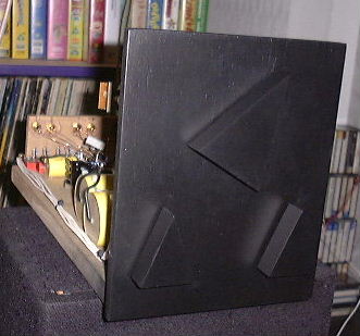
front panel - MDF sprayed and sanded and sprayed and
sanded and ... It looks a lot better than it does here - makes
for a nice finish. Car matt black spray. Balance, i/p select and
the big one is volume (11 steps only)
The
front panel - MDF sprayed and sanded and sprayed and
sanded and ... It looks a lot better than it does here - makes
for a nice finish. Car matt black spray. Balance, i/p select and
the big one is volume (11 steps only)My Bride of Zen is a great little unit - hot melt glue the 1000uF caps and the MOSFET heatsinks (it doesn't get too hot to melt the glue!!!) to an MDF 'chassis' and construct the rest directly onto these bits! PCB or other techniques have no place here (IMHO). Used a star ground with both channels constructed adjacent, using the PSU exactly as Nelson's design. No hum whatsoever. Quite a bit of crud from local FM transmitter, gets everywhere. The PSU is again remote, within the chassis that also serves the Zen amp
The simpicity of the electronics gave me time to make some smart black triangular knobs from sprayed MDF.
A few pics... (Imagine it nestling in with those vids at the back - who needs sides, a top etc?)
The
front panel - MDF sprayed and sanded and sprayed and
sanded and ... It looks a lot better than it does here - makes
for a nice finish. Car matt black spray. Balance, i/p select and
the big one is volume (11 steps only)
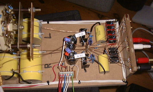 The
guts, such as they are. Shows the parallel (dual mono
apart from earth) construction. Star ground shows well. 1000uF
PSU caps decoupled with 2.2uF polyester (orange) & 47uF elec
(blue). All internal wiring done with the 38SWG enamelled copper
wire. Silver next? One day.. I beefed the o/p caps up to 25uF to
drive the paralleled Zens without zapping too much bass - we are
into marginal territory here with only 10uF and a 500ohm o/p load
at max volume.
The
guts, such as they are. Shows the parallel (dual mono
apart from earth) construction. Star ground shows well. 1000uF
PSU caps decoupled with 2.2uF polyester (orange) & 47uF elec
(blue). All internal wiring done with the 38SWG enamelled copper
wire. Silver next? One day.. I beefed the o/p caps up to 25uF to
drive the paralleled Zens without zapping too much bass - we are
into marginal territory here with only 10uF and a 500ohm o/p load
at max volume.
 More
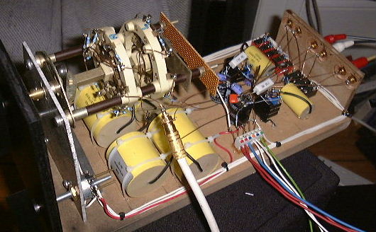
guts. Only a single output cable in this pic. Neat
volume selector switch! All i/p switching done with 12V telecom
grade relays (seen at back of unit under i/ps), and balance
control too -3, -1.5, 0, +1.5, +3dB.
More
guts. Only a single output cable in this pic. Neat
volume selector switch! All i/p switching done with 12V telecom
grade relays (seen at back of unit under i/ps), and balance
control too -3, -1.5, 0, +1.5, +3dB.
'Shunt' balance control: I did a simple shunt
balance control, both channels go via 2k2 resistor after the i/p
select relays. In centre (balanced) position, this resistor is
all that the signal sees. In the unbalanced positions (-3, -1.5,
+1.5, +3dB), the 'cold' end of this resistor is pulled to ground
by an appropriate resistor to achieve the required gain drop. So
with balance control to the left, the R channel is pulled down (L
channel is left unchanged i.e. straight through), and vice versa
for the balance control to the right. Switching is controlled by
miniture telecoms relays, seen at the rear, beneath the i/p sockets.
Summary: Have to say this
thing works like a dream, and has no difficulty swinging massive
amounts of signal into the Zen. No problem with overload - it
handles the 0dB test tracks from my test CD without any clipping.
5.78V PP i/p gives 36.88V PP o/p into 5K. This will fall as the
volume is increased due to loading by the Zen (and the
theoretical gain falls too). For the record I have the MOSFET
biased to 31V (Drain to ground) with R104 at 767Ohm (1k || 3k3)
and a 63V supply. Otherwise as per original design.
Update: Jun 2013: Checked harmonic distortion with spectrum analyser, not too bad as adjusted manually, but tweaked it down some more, with V(R104) around 29.4V. This is at odds with the 20V in the original article, but it's definitely at the distortion minimum. I don't recall excactly but think I originally adjusted it (in 2001) with just a scope so that the test sine wave 'looked about right' (and sounded ok too!).
Nice one Nelson!
Link back to main Zen Revisited amp page
So has this been of use or interest to anyone? Please take a moment to mail me if so..